


|
|
 |
|
Welcome to the GSM-Forum forums. You are currently viewing our boards as a guest which gives you limited access to view most discussions and access our other features. Only registered members may post questions, contact other members or search our database of over 8 million posts. Registration is fast, simple and absolutely free so please - Click to REGISTER! If you have any problems with the registration process or your account login, please contact contact us . |
| |||||||
| Register | FAQ | Donate | Forum Rules | Root any Device | ★iPhone Unlock★ | ★ Direct Codes ★ | Direct Unlock Source |
| | LinkBack | Thread Tools | Display Modes |
 05-02-2014, 07:31
| #1 (permalink) |
| No Life Poster  Join Date: Sep 2008
Posts: 822
Member: 860880 Status: Offline Thanks Meter: 83 | Atf 5 in 1 cable emmc connection problem please clarify 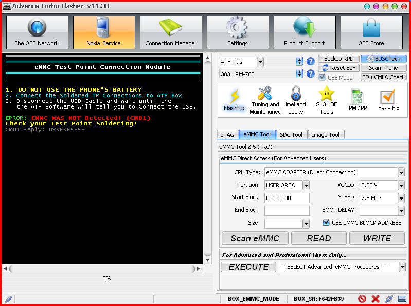 |
|
05-02-2014, 11:42
| #2 (permalink) |
| No Life Poster Join Date: Apr 2011 Age: 58
Posts: 16,408
Member: 1564612 Status: Offline Thanks Meter: 12,343  | Bro, this adapter have all pinout wrong, only GND is right... i've see the difference in one post but not remember where... you can see RIGHT pinout from RJ45 by X-Shadow here: RJ-45 PINOUT During EMMC_MODE 1 - NOT USED (VBATT) 2 - Connect to eMMC Vcc and VccQ (Adjustable Power Supply) 3 - NOT USED 4 - Auxilliary CLK (Optional) 5 - CMD 6 - Primary CLK 7 - GND 8 - DATA_0 http://forum.gsmhosting.com/vbb/9761301-post4.html BR allumts |
|
05-02-2014, 11:46
| #3 (permalink) |
| No Life Poster Join Date: Apr 2011 Age: 58
Posts: 16,408
Member: 1564612 Status: Offline Thanks Meter: 12,343 | @mobifone, here the post, but remember that Search button is a good friend: http://forum.gsmhosting.com/vbb/10205970-post52.html Br allumts |
| The Following User Says Thank You to allumts For This Useful Post: |
|
05-02-2014, 12:47
| #6 (permalink) |
| Freak Poster  Join Date: Jan 2013 Location: Switzerland Age: 48
Posts: 408
Member: 1873863 Status: Offline Thanks Meter: 67 | mobifone i have bought the atf 5in1 and made the post on the link above. First you have to cut the line that goes from 5V to CMD, otherwise you risk to burn the emmc. Then you should resolder each RJ45 cable with the correct configuration, and make a bridge from the free wire to CMD. I have bought from GPG thinking it was a good product, but is a ***** |
|
05-02-2014, 13:18
| #8 (permalink) |
| Freak Poster Join Date: Jan 2013 Location: Switzerland Age: 48
Posts: 408
Member: 1873863 Status: Offline Thanks Meter: 67 | Ok, this afternoon i will post a picture of my modified interface. It is different from the original, because i have removed the power ic that gives 1.8v to use it on a custom board. My GPG ATF5in1 now have only the 3.3v power ic, because i needed a second interface to use when i connect directly to the emmc when is on pcb , but i will show you where i have cut the 5V line and where i have bridged CMD. I have doubts that JTAG and SD will work too with this interface, but i don't need them so i don't guarantee to you that this will work again after the modifications. |
| The Following User Says Thank You to laptopmd For This Useful Post: |
|
05-03-2014, 06:32
| #9 (permalink) |
| No Life Poster Join Date: Sep 2008
Posts: 822
Member: 860880 Status: Offline Thanks Meter: 83 | Hope gpg industries will comment/clarify on the subject and clearly tell what modification should be done so we can use the cable and all its features .over to you gpg to save your reputaion |
|
05-03-2014, 11:39
| #10 (permalink) | |
| No Life Poster Join Date: Apr 2011 Age: 58
Posts: 16,408
Member: 1564612 Status: Offline Thanks Meter: 12,343 | Quote:
Br allumts | |
|
05-03-2014, 12:38
| #11 (permalink) |
| Freak Poster Join Date: Jan 2013 Location: Switzerland Age: 48
Posts: 408
Member: 1873863 Status: Offline Thanks Meter: 67 | here the picture that mobifone requested, this is how it look my interface now. the 1.8v power regulator is missing because i needed for another homemade interface, but you can leave it here if you want. I have cut the track on pcb between 5V and cmd, then i removed the pin connector and made a bridge between tms and cmd I have desoldered the wires and resoldered on the right scheme, my wires are now : 1 - White 3 - Black 5 - Blue 7 - Brown 8 - Green I USE ATF NITRO, don't know if this is the same for the big box ATF. BR Dave IMG_0242.jpg P.s. : if you still have connection problems, you can solder two 100ohm pull-up resistors between 3.3v pin and CMD and DATA0 |
|
05-03-2014, 13:03
| #12 (permalink) | |
| No Life Poster Join Date: Apr 2011 Age: 58
Posts: 16,408
Member: 1564612 Status: Offline Thanks Meter: 12,343 | Quote:
 Br allumts | |
|
05-03-2014, 13:27
| #14 (permalink) | ||
| No Life Poster Join Date: Apr 2011 Age: 58
Posts: 16,408
Member: 1564612 Status: Offline Thanks Meter: 12,343 | Quote:
1) Quote:
@laptopmd, what the wire can i see down the 3V3 point? Br allumts | ||
| The Following User Says Thank You to allumts For This Useful Post: |
|
05-03-2014, 13:31
| #15 (permalink) |
| Freak Poster Join Date: Jan 2013 Location: Switzerland Age: 48
Posts: 408
Member: 1873863 Status: Offline Thanks Meter: 67 | 2) No no you can leave U1 here, so you have 1.8v pin too. I needed U1 on another board so i have removed it. Leave it here  @allumts : i don't have understood your question... |
| The Following User Says Thank You to laptopmd For This Useful Post: |
| Bookmarks |
| |
|
|


 Linear Mode


