


|
|
 |
|
Welcome to the GSM-Forum forums. You are currently viewing our boards as a guest which gives you limited access to view most discussions and access our other features. Only registered members may post questions, contact other members or search our database of over 8 million posts. Registration is fast, simple and absolutely free so please - Click to REGISTER! If you have any problems with the registration process or your account login, please contact contact us . |
| |||||||
| Register | FAQ | Donate | Forum Rules | Root any Device | ★iPhone Unlock★ | ★ Direct Codes ★ | Direct Unlock Source |
| iPhone, iPad, iPod Hardware Repair Hardware Repair discussions for iPhone, iPod , iPad & Apple Products, help, guides. |
 |
| | LinkBack | Thread Tools | Display Modes |
 07-07-2016, 03:22
| #31 (permalink) |
| Junior Member  Join Date: Jun 2016 Location: Illinois
Posts: 37
Member: 2591312 Status: Offline Thanks Meter: 2 | |
 |
|
07-07-2016, 03:25
| #32 (permalink) |
| Junior Member Join Date: Jun 2016 Location: Illinois
Posts: 37
Member: 2591312 Status: Offline Thanks Meter: 2 | What is the secret to soldering jumper wires from pin 1 to Pin 5 on the Q8104 chip. I can not get my wires to stick. It keeps coming off the pads. I have my soldering iron set at 750 - 780 degrees. What am I doing wrong? |
| |
|
07-07-2016, 05:11
| #33 (permalink) |
| Junior Member Join Date: Jun 2016 Location: Illinois
Posts: 37
Member: 2591312 Status: Offline Thanks Meter: 2 | I don't know why previous question posted several times. Anyways since I could not get my wires to stick I used a pair of thin insulated tweezers to short pin 1 to pin 5 on Q8104. Here is what I did and the results from test. First I connected the RED test from multimeter to the + Battery tab and BLACK test from the multimeter to GND. Powered on logic board and carefully shorted pin 1 to pin 5 on Q8104 and got a reading of 4.94v at the + Battery tab. Does this test confirm that Q8104 is bad? |
| |
|
07-07-2016, 05:27
| #34 (permalink) | |
| Freak Poster Join Date: Sep 2014 Location: CN & NZ
Posts: 388
Member: 2252373 Status: Offline Thanks Meter: 400 | Quote:
 | |
| |
|
07-07-2016, 05:40
| #35 (permalink) |
| Freak Poster Join Date: Sep 2014 Location: CN & NZ
Posts: 388
Member: 2252373 Status: Offline Thanks Meter: 400 | Q8104 pin 1 = 4.94v is no right, only 4.2V is okay. please take 1 or more photos include: charger + cable + dock flex + logic board Let us know how you are going to test it. |
| |
|
07-07-2016, 06:04
| #36 (permalink) | |
| Freak Poster Join Date: Sep 2014 Location: CN & NZ
Posts: 388
Member: 2252373 Status: Offline Thanks Meter: 400 | Quote:
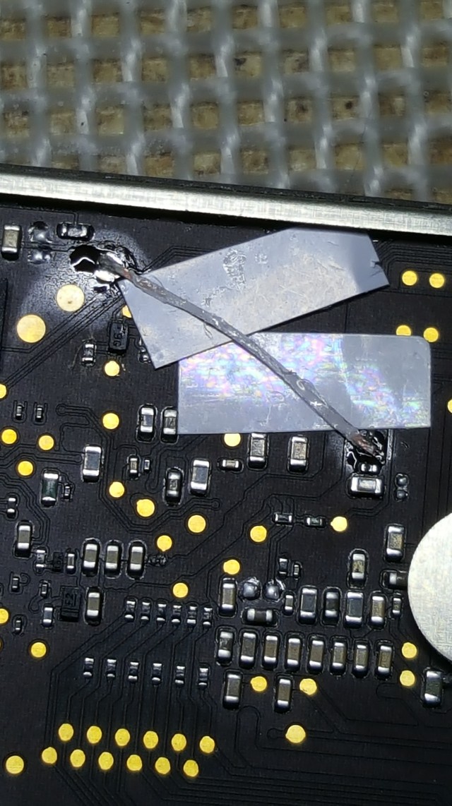
if Q8104 faulty, We have different way to repair it. 1, replace it, u need new Q8104 part (Level 3 / Component level repair) 2, remove it, jumbing pin1-2-3 to pin 5 (Level 3 / Component level repair) Way 1 & 2 is General Way, no need many experiences of schematics 3, dont need remove the Q8104, only jumbing anyone way of PPVCC_MAIN to PPBATT_VCC , like before u do or C8165 to C8101 or Q8104 pin 1 to C8101. (Level 4 / PCB level repair) Way 3 is higher level for repair, need many experiences and knowledge of schematics. It is clear, using way 3 to fix which is faster, lower risk, easier. | |
| |
|
07-08-2016, 00:25
| #37 (permalink) |
| Junior Member Join Date: Jun 2016 Location: Illinois
Posts: 37
Member: 2591312 Status: Offline Thanks Meter: 2 | I will be uploading several pictures that you wanted to see 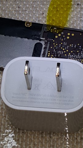 This is a 5v plug adapter 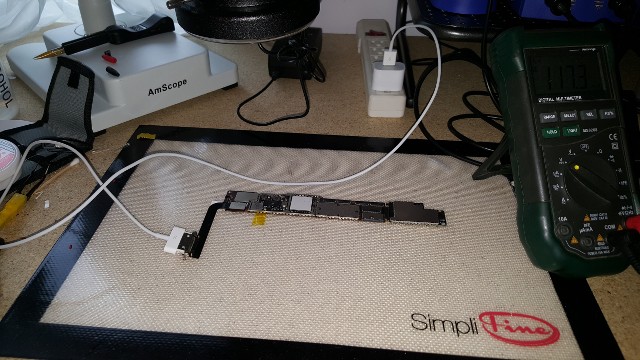 Flex connector and plug view 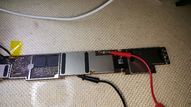 View of how I have the test leads in position to measure the voltage when I short Pin 1 to Pin 5 on Q8104. 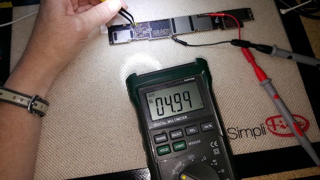 Photo when logic board is live and measuring + Battery to GND, when I short pin 1 to pin 5 to Q8104. Last edited by LetItFlowTech; 07-08-2016 at 00:30. |
| |
|
07-08-2016, 00:36
| #38 (permalink) |
| Junior Member Join Date: Jun 2016 Location: Illinois
Posts: 37
Member: 2591312 Status: Offline Thanks Meter: 2 | What would be causing 4.99 volt reading? Bad Q8104 chip. Did you see my resistance reading on the capacitors I took early in the post? Where those values within good range? When I take Q8104 reading when nothing is shorted, I do get 3.74 volts across pins 1, 2 and 3 but nothing on the pin 5. So I shorted Pin 1 to Pin 5 on Q8104 and I do get reading, but its close to 5v and you say its took high. What else should I look at? |
| |
|
07-08-2016, 04:04
| #39 (permalink) | |
| Freak Poster Join Date: Sep 2014 Location: CN & NZ
Posts: 388
Member: 2252373 Status: Offline Thanks Meter: 400 | Quote:
check 1-7 key points again 1 / 5v -- > 2 / 5v -->3 / 5v -->4 /3.7-4.2v --> 5 / 3.7-4.2v --> 6 / 3.7-4.2v --> 7 / 3.7-4.2v --> battery | |
| |
|
07-08-2016, 06:37
| #40 (permalink) |
| Junior Member Join Date: Jun 2016 Location: Illinois
Posts: 37
Member: 2591312 Status: Offline Thanks Meter: 2 | Should I re-check points 1 through 7 with pin 1 shorted to pin 5 or just re-check the points just regularly without shorting any capacitors or shorting any pins on the Q8104 chip |
| |
|
07-09-2016, 23:46
| #41 (permalink) |
| Junior Member Join Date: Jun 2016 Location: Illinois
Posts: 37
Member: 2591312 Status: Offline Thanks Meter: 2 | Hey JimChu316 I re-tested the key points again. No jumpers or shorts were performed during the test. Here are the results TP1 - GND to L5757 = 5.06V TP2 - GND to 8123 = Pins 1,2 & 3 = 5.06V, Pin 4 = 0V, Pin 5 = 5.06V TP3 - GND to U8100 = could not access pins on U8100 chip. TP4 - GND to L8112 = 3.76V TP5 - GND to Q8104 = Pins 1,2 & 3 = 3.73V, Pin 4 =3.73V, Pin 5 = 0V TP6 - GND to + BATTERY = 0V |
| |
|
07-10-2016, 02:06
| #42 (permalink) | |
| Freak Poster Join Date: Sep 2014 Location: CN & NZ
Posts: 388
Member: 2252373 Status: Offline Thanks Meter: 400 | Quote:
after jumbing, to test the battery, if <3.5V, using DC 3.5-4.0V charging battery. and the 1A charger your using is not right, 1A charger only for iphone, iPad need 2A charger. Last edited by jimchu316; 07-10-2016 at 02:12. | |
| |
|
07-10-2016, 06:21
| #43 (permalink) |
| Junior Member Join Date: Jun 2016 Location: Illinois
Posts: 37
Member: 2591312 Status: Offline Thanks Meter: 2 | So you want me to jump pin 1 to pin 5 on Q8104 again and take another measurement from GND to + BATTERY? I will pull out the other charger which is 12W - 5V output 2.4A. |
| |
|
07-10-2016, 13:40
| #44 (permalink) | |
| Freak Poster Join Date: Sep 2014 Location: CN & NZ
Posts: 388
Member: 2252373 Status: Offline Thanks Meter: 400 | Quote:
| |
| |
|
07-11-2016, 20:35
| #45 (permalink) |
| Junior Member Join Date: Jun 2016 Location: Illinois
Posts: 37
Member: 2591312 Status: Offline Thanks Meter: 2 | Ok re-ran my test morning using 12W , 5V, 2.4A power adapter. Jumped pin 1 to pin 5 on Q8104 and took my voltage reading across +Battery to GND and got 4.89 to 4.90v reading at +Battery. Does this sound like a failed Q8104 chip to you? |
| |
| The Following User Says Thank You to LetItFlowTech For This Useful Post: |
|
| Bookmarks |
| |
|
|


 Linear Mode


