


|
|
 |
|
Welcome to the GSM-Forum forums. You are currently viewing our boards as a guest which gives you limited access to view most discussions and access our other features. Only registered members may post questions, contact other members or search our database of over 8 million posts. Registration is fast, simple and absolutely free so please - Click to REGISTER! If you have any problems with the registration process or your account login, please contact contact us . |
| |||||||
| Register | FAQ | Donate | Forum Rules | Root any Device | ★iPhone Unlock★ | ★ Direct Codes ★ | Direct Unlock Source | Mark Forums Read |
| Easy-Jtag / Easy-Jtag Plus The official support section. You can ask here your question and get answer regarding using Easy-Jtag / Easy-Jtag Plus. |
 |
| | LinkBack | Thread Tools | Display Modes |
 05-21-2013, 17:30
| #1 (permalink) |
| Product Supporter  Join Date: Mar 2005 Location: China
Posts: 3,338
Member: 129885 Status: Offline Sonork: 100:1603514 Thanks Meter: 6,202 | 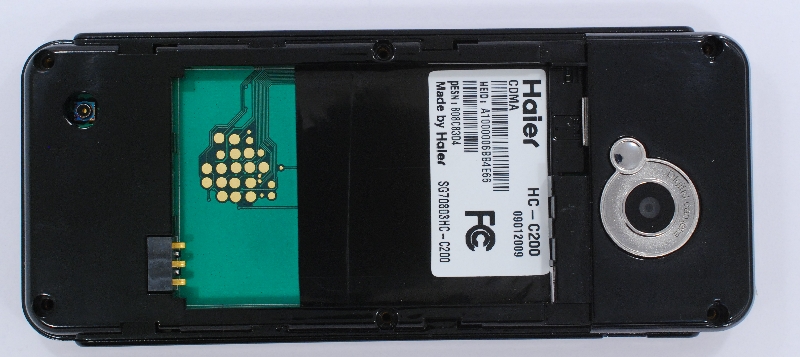 Finding JTAG may need some steps before you solder any pins ;-) You need some additional tools like multimeter [IMG]http://4.bp.********.com/-GbDO8OqTJ8Y/UEyboG-xbUI/AAAAAAAAChY/HmedxGWOWbo/s1600/Multimeter.jpg[/IMG] Before soldering we need to probe some important PINS: GROUND ( Must be always connected to PIN20 ) BATTERY+ ( Must be excluded from search , because high currect may break box logic ) RESET ( Must be excluded from search , because powers off JTAG and finder may fail to detect JTAG. ) For this i've made more detailed photo of testpoint area  With MULTIMETER in diode probing mode I am detected ground pin (blue) and reset pin ( violet) Every time if you touch this pin phone go in restart. GND and BATTERY TPs are easy to detect by multimeter , they directly wired on battery terminals. NRST are easy to detect while looking on phone screen and tapping all testpoints one by one. Phone will restart every time you tap NRESET pin. Most powerful method are connect testpionts to GND via 1kOm resistor but in most situation enough to tap by tweezers or multimeter probe. I am marked them on picture : 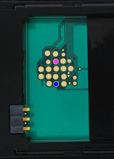 Then I am numbered rest of test points on PCB and soldered them to EasyJTAG box header one by one: 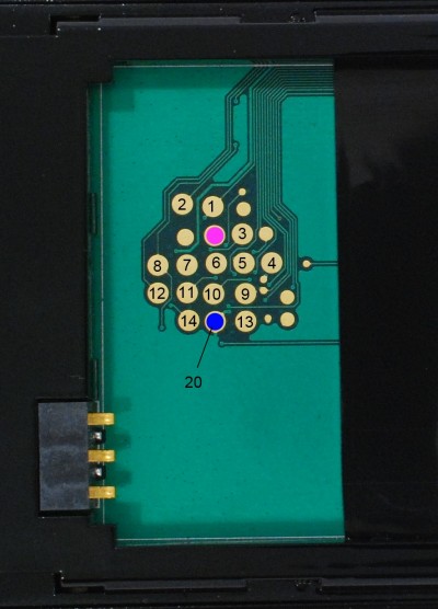 Connected phone to power source and tried to search pin out - and it was succeseful  All JTAG pins are detected , and we know position of GND and NRST before. All JTAG pins are detected , and we know position of GND and NRST before.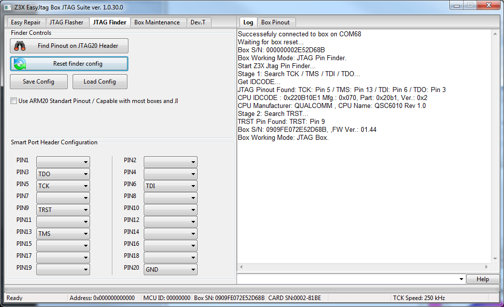 Next step to solder one of free pins ( ex. PIN1 ) to reset TP , define SRST to PIN1 in software and try to connect phone like nearest models with same MCU : QSC6010 For example as HAIER HC-C2030.  Now we got success connection from first try ;-) 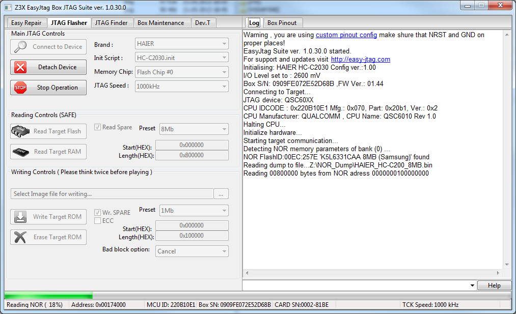 And finally we get HAIER HC-C200 JTAG Pinout World First by Z3X TEAM : 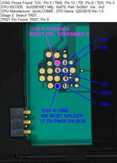 Last edited by NoName®; 05-21-2013 at 20:09. |
 |
| The Following 11 Users Say Thank You to NoName® For This Useful Post: |
|
06-17-2013, 05:58
| #4 (permalink) |
| Insane Poster  Join Date: May 2012 Location: USA
Posts: 66
Member: 1754897 Status: Offline Sonork: 100.1622738 Thanks Meter: 5 | Easy JTAG Finder Question I am attempting to locate the pinout on an LG MS910. I was able to get Easy JTAG to identify the pins in Stage 1, but when looking for TRST in Stage 2, it identified Pin 2 as TRST, which was identified as TCK during Stage 1. Here is the log: Start Z3X Jtag Pin Finder... Successefuly connected to box on COM39 Waiting for box reset... Box S/N: 00000000BXXXX (it's valid) Box Working Mode: JTAG Pin Finder. Start Z3X Jtag Pin Finder... Stage 1: Search TCK / TMS / TDI / TDO... Get IDCODE... JTAG Pinout Found: TCK: Pin 2 / TMS: Pin 7 / TDI: Pin 8 / TDO: Pin 6 CPU IDCODE : 0x27B360E1 Mfg.: 0x070, Part: 0x7b36, Ver.: 0x2 CPU Manufacturer: QUALCOMM , CPU Name: MSM8255 Scorpion Rev 2.0 Stage 2: Search TRST... TRST Pin Found: TRST: Pin 2 Box S/N: 00000000BXXXX (it's valid), ,FW Ver.: 01.44 Box Working Mode: JTAG Box. So is pin 2 TCK or TRST? if TCK, how do I find TRST. If pin 2 is TRST, how do I find TCK? During this test, BAT. and NRST WERE NOT connected to the Easy-JTAG box. Pin 20 was set to GND. Suggestions? |
| |
|
06-17-2013, 08:54
| #5 (permalink) |
| Product Supporter Join Date: Mar 2005 Location: China
Posts: 3,338
Member: 129885 Status: Offline Sonork: 100:1603514 Thanks Meter: 6,202 | Hi , offcource PIN2 are TCK and TRST has been detected wrong. At this moment you can try to select TRST pin on different position manyally. This CPU are multicore and detecting pinout on such CPUs will be improved in next box firmware. |
| |
| The Following 3 Users Say Thank You to NoName® For This Useful Post: |
|
07-22-2013, 00:04
| #8 (permalink) | |
| Product Supporter Join Date: Mar 2005 Location: China
Posts: 3,338
Member: 129885 Status: Offline Sonork: 100:1603514 Thanks Meter: 6,202 | Quote:
| |
| |
| The Following User Says Thank You to NoName® For This Useful Post: |
|
08-04-2013, 22:20
| #10 (permalink) | |
| Product Supporter Join Date: Mar 2005 Location: China
Posts: 3,338
Member: 129885 Status: Offline Sonork: 100:1603514 Thanks Meter: 6,202 | Quote:
| |
| |
|
08-05-2013, 10:07
| #11 (permalink) |
| Junior Member Join Date: Jan 2012
Posts: 25
Member: 1713721 Status: Offline Thanks Meter: 8 | Hello, primarily seek support for Garmin GPS. I think there is a very similar jtag port on all Garmin gps. Do not know if it would be possible to get a shematic of some garmin gps model to verify. The phones are many schematics, but no gps. To debrick and support debug, like functions (breakpoints, step, read registers etc. ..) thx for your interest. |
| |
|
08-07-2013, 05:57
| #12 (permalink) | |
| Freak Poster Join Date: Feb 2009 Location: lake
Posts: 327
Member: 983215 Status: Offline Thanks Meter: 49 | Quote:
Hello, the cable for Jtag header[ gpgcable=10pins] if you take out v+ and Gnd pins you are left with 8pins to work with for searching pinouts. Now my question is, in the above Haier c200 example you have numbered the pin pads on the phone board from 1 to 14 and they are all possible pinouts and we are having only 8pins from the header cable which if we solder there will be still six tp on pcb left empty which might be part of the correct pinouts. How do you solve that? how do you have all the tpoints wired if they are 14....12...0r 15 so you avoid pin search failed and many endless trials? the header has 20 pins in total but you have numerous GND and NC its like you can not expand it to increase the number of pins for searching to atleast 12 or 18? or is it possible? b.r viniicell | |
| |
|
| Bookmarks |
| Thread Tools | |
| Display Modes | |
| |
|
|


 Linear Mode


