


|
|
 |
|
Welcome to the GSM-Forum forums. You are currently viewing our boards as a guest which gives you limited access to view most discussions and access our other features. Only registered members may post questions, contact other members or search our database of over 8 million posts. Registration is fast, simple and absolutely free so please - Click to REGISTER! If you have any problems with the registration process or your account login, please contact contact us . |
| |||||||
| Register | FAQ | Donate | Forum Rules | Root any Device | ★iPhone Unlock★ | ★ Direct Codes ★ | Direct Unlock Source |
| BlackBerry (RIM) Blackberry phones discussion, firmwares, tutorial, media, repairs. |
 |
| | LinkBack | Thread Tools | Display Modes |
 07-02-2009, 15:32
| #1 (permalink) |
| No Life Poster  Join Date: Oct 2004 Location: Dominica, West Indies Age: 63
Posts: 646
Member: 88701 Status: Offline Thanks Meter: 381 | BB USB Port Schematic 8100 This may be of help to someone repairing the USB port...when the connection pads on the PCB are MISSING  I only managed to locate the connection points for D+ and D- Need some more work to find the USB V+ connection and the USB ID connection Note... you can remove this chip shown on the pic and solder your connections to its output pads. Im almost certain that this chip is an ESD filter which is in series with the USB Port. There are no skems for BB !....so if anyone can please add on to this thread to locate the USB V+ and USB ID connection 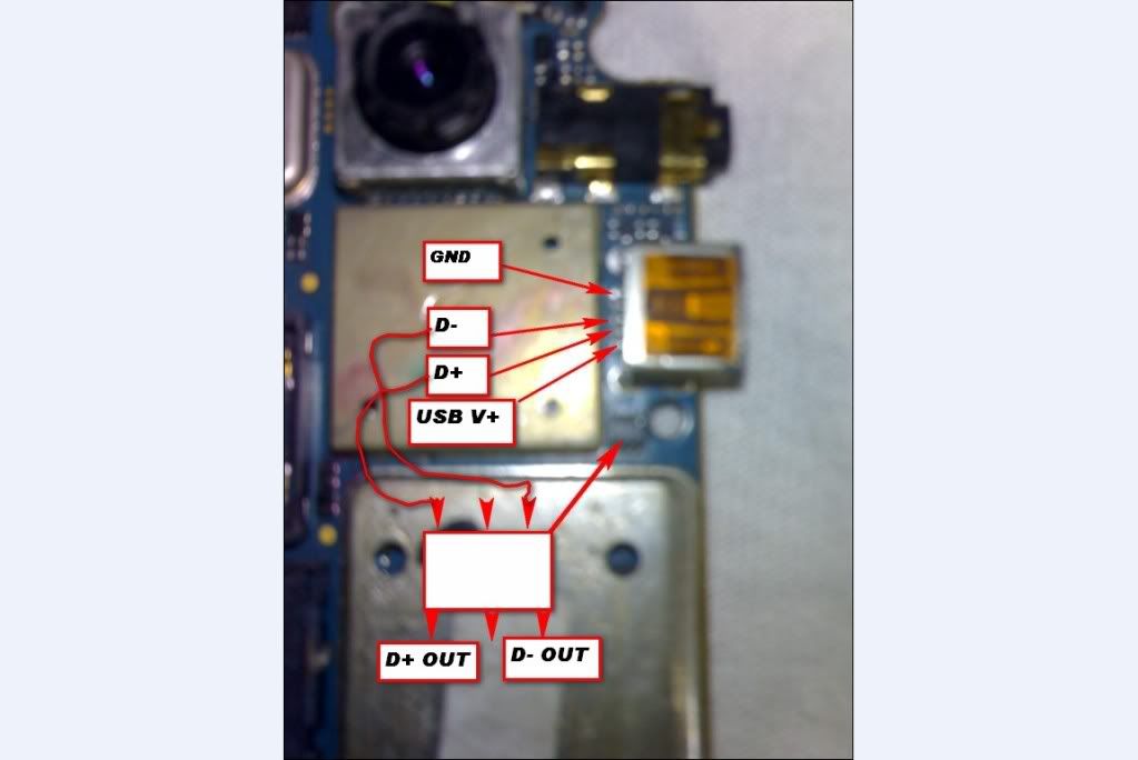 ;smokin |
 |
| The Following 3 Users Say Thank You to Orange_Dominica For This Useful Post: |
|
07-06-2009, 14:39
| #5 (permalink) |
| No Life Poster Join Date: Oct 2004 Location: Dominica, West Indies Age: 63
Posts: 646
Member: 88701 Status: Offline Thanks Meter: 381 | Found USB PWR According to the diagram..it looks like BB dosent make use of pin 4 USB ID. In that case.. just by applying voltage and GND, the BB should go into the charge mode Excellent work MR. SDTV ! Your time and knowledge is honored This post may help out someone when the USB port is hosed ;smokin Last edited by Orange_Dominica; 07-06-2009 at 14:46. |
| |
|
07-23-2009, 17:42
| #6 (permalink) |
| Junior Member Join Date: Jul 2009
Posts: 1
Member: 1081120 Status: Offline Thanks Meter: 0 | is this really need to move the chip for connect direct from USB port to D+ and D-, I did what is on the picture, but it only charge the phone, ( not remove the chip, just solder direct to the out put). the DM couldn't work. or computer couldn't find the device. |
| |
|
12-05-2009, 19:17
| #8 (permalink) |
| Junior Member  Join Date: Jun 2007
Posts: 37
Member: 526513 Status: Offline Thanks Meter: 10 | mmmUUuUuuhhHHaAAA i LOVE YOU DEAR THIS IS MOST IMPONTENT FOR MY CELL PHONE I LIKE YOUR SEARCH YOUR TOO COOL KEEP IT UP IF YOU A CELL NUMBER NO# PLEASE SEND ME AND YOUR YAHOO ID.... |
| |
|
| Bookmarks |
| |
 Similar Threads
 | ||||
| Thread | Thread Starter | Forum | Replies | Last Post |
| Furious-Gold Box ---> USB not recognized when plugged into USB Port | Hanukkah | FuriousGold | 15 | 03-15-2007 04:04 |
| RJ45 Port Not responding, Usb Port OK | blaiseid | Smart-Clip | 24 | 12-25-2005 18:09 |
| Red Box and USB port | tical | Redbox | 3 | 08-29-2004 13:23 |
| Simulate an USB-Port | JES01 | Samsung Flashers, Software, Firmware. | 2 | 08-24-2004 17:27 |
|
|


 Linear Mode


